External Mount Cleanroom Sliding Door Installation & Setup
1. Safety & Proprietary Notices
Critical Operation Conditions
- Ensure the rough opening is capable of providing proper structural support.
- Only a qualified service technician should make repairs to surrounding electrical cables and/or other surrounding structure to verify the proper anchoring of the unit before installation.
- Disconnect the power supply before servicing.
- Consult local building code officials for applicable building codes and regulations.
- Local building code requirements supersede recommended installation instructions.
- Doors are intended for use in positive or negative-pressure cleanrooms where air movement is acceptable.
Disclaimer: This manual pertains to proprietary devices manufactured by Terra Universal, Inc. Neither this document nor any portion of it may be reproduced in any way without prior written permission from Terra Universal.
Disclaimer: Terra Universal makes no warranties applying to the information contained in this manual or its suitability for any implied or inferred purpose. Terra Universal shall not be held liable for any errors this manual contains or for any damages that result from its use.
2. Automatic Sliding Door Overview
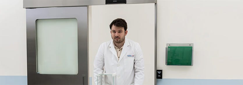
Terra's automatic sliding doors are ideal for high-traffic areas and are intended for use in positive or negative-pressure cleanrooms where air movement is acceptable. They include either an external or recessed mount with automatic or manual operation.
External-mounted doors are well-suited for retrofit construction whereas recessed doors are ideal for room partitions or openings larger than the desired door size. They are available in aluminum or stainless steel frames with either tempered glass or static-dissipative polyvinyl chloride door panels. Doors include load-bearing wheels made of cast urethane for long-lasting, smooth, and trouble-free operation. Terra has specially designed its doors pre-hung to frames to allow quick, seamless, and non-intrusive installation
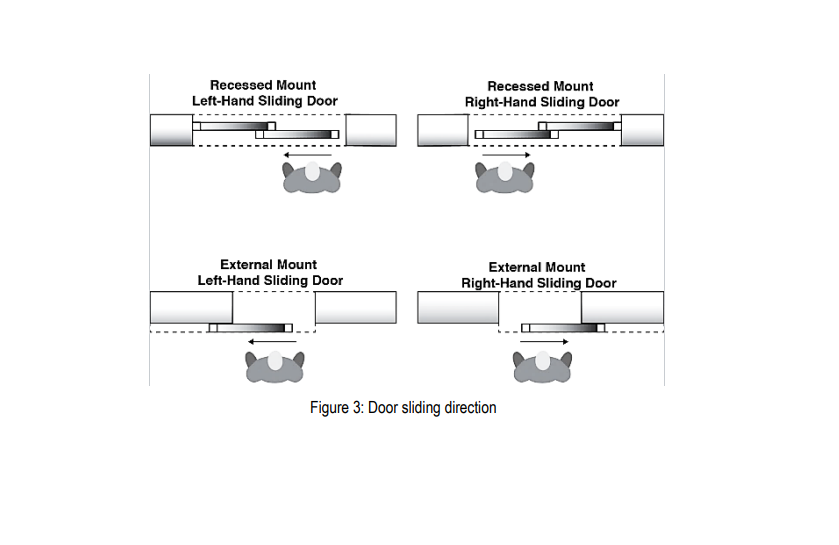
2.1 External Mount Doors Overview
The door track is mounted externally to the wall surface and is well suited for retrofit construction and easy installation where a large opening is not possible for recessed door frames. The system requires enough empty wall space next to the opening to allow door(s) to slide completely open.
The microprocessor controller continually monitors door position with adjustable features such as:
- Opening and closing speed.
- Distance and speed of braking.
- Reducing opening and time delay.
The unit arrives with the pre-assembled header and panel sub-assemblies. The adjustable anti-rise wheels lock each door in its overhead track and undergo life testing to a minimum of one million cycles.
Manual External Mount Cleanroom Doors
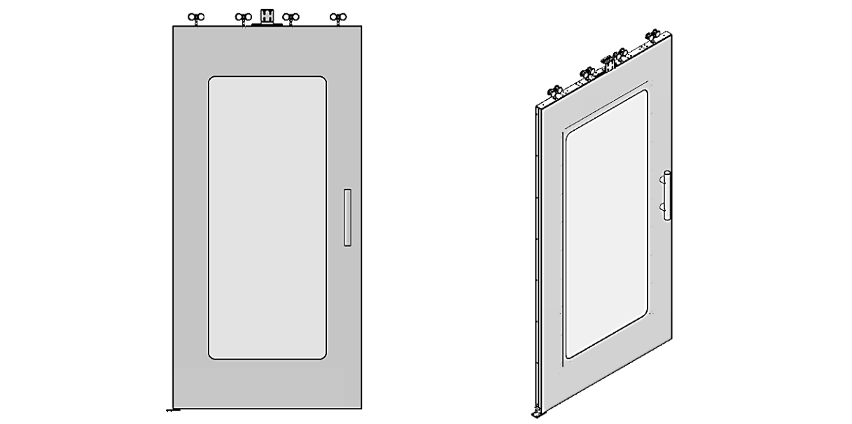
Manual external mount doors use 304 stainless steel and include left or right sliding options as well as load-bearing wheels made of cast urethane for long-lasting, smooth, and trouble-free operation. 304 Stainless steel stands up to common disinfectants and the door assembly includes the frame and track that are installed inside the existing wall cutout/partition.
For strict cleanliness protocols, BioSafe® windows forego shoddy spot-welding in favor of dual-pane glass installed flush on steel for a continuously smooth surface. The wall cut-out size for the doors should be at least 81” in height and 36” width.
Automatic External Mount Sliding Doors include adjustable anti-riser wheels that lock each door in the overhead track as well as auto reverse and slow speed search for obstruction. The elastomeric door seals and fiberglass reinforced timing belt ensure cleanliness, durability and uniform closing. All automatic doors use the hand wave sensor to open the doors and the ESA II Revive kit to prevent the door from closing on someone when that person is entering or leaving. Static dissipative PVC door panels enhance static and particle control, stand up to cleaning agents, minimize obstructive sight line and reduce claustrophobic sensation in small rooms. These doors are ideal for aseptic cleanrooms that require hands-free door operation available with several different styles.
2.2 Pre-hung Recessed Doors
The door frame and track are installed inside the existing wall cutout/partition with a touchless motion door pad for hands-free operation. These doors are well-suited for room partitions or openings larger than desired door size and can be configured to include side lights for additional visibility. The toothed drive belt reinforced with fiberglass prevents slippage and ensures even closing. These doors arrive with a pre-assembled header and panel sub-assemblies.
- Recessed doors use an Optex X-Zone T sensor for door operation and a single-point bottom rail deadlock(s) electric locking. Manual recessed doors include left/right sliding options and are pre-assembled.
- Doors purchased prior to March 2019 use a Stanley SU-100 motion sensor or Stan-Guard® Threshold sensor.
2.3 Part Numbers Covered by this Manual
See full PDF (Pg. 8 - 9) for list of part numbers covered by this manual.
3. Installation Steps: External Mount Sliding Door
3.1 External Mount Sliding Door Installation Steps
Note: Carefully disconnect the wires for the logo, motion sensor, and program switches.
- Remove screws from the top and the sides of the cover to access the frame
- Locate the struts in the wall – insert screw through the designated slots.
- Drop the frame onto the mounting bracket
- Fasten the Z bracket to the mounting bracket to prevent the frame from tilting.
- Create cutout on the wall for the power cables.
- Unfasten the nuts that are underneath the door stoppers and remove from the track.
- Carefully unwrap the door and remove the screws and nuts attached on the bracket.
- Align the bracket on the door with the bracket on the belt. Proceed to use the screws and nuts that were on the door to attach them together.
- Slide the door open until door is flushed with the edge of the frame.
- Reattach the door stopper and adjust its location until the door hits it when it is fully open. Secure the door stopper - tighten the nuts.
- Adjust the door guide so the door will slide straight; fasten door guide to the wall with provided screws.
- Close the door completely; place the sliding door guide halfway into the door and screw down to the floor.
- Install the provided cover plate.
- Rewire any loose wires and tidy up with zip ties.
- Put the cover back on. Hold the cover in place by putting the screws back on.
3.2 Door Operator Installation – ESA II Revive Slider Conversion Kit
- Remove DC power supply plug from its socket on ESA II controller.
- Remove program switch plug from its socket on ESA II controller.
- Note: Door will be in CLOSE (OFF) position.
- Electric shock hazard! 115VAC disconnect to the branch circuit supplying power to ESA must be OFF prior to installing and during electrical wiring installation.
- DC power supply plug must be removed from its socket (See step 1).
- The program switch plug must be removed from its socket (See step 2).
- Pull out 115 VAC connector with strain relief from connector attached to DC power supply.
- Cut jacket insulation from customer 115 VAC wiring.
- Strip 3/8” (9 mm) insulation from end of L and N wires.
- Remove strain relief cover and bottom section (secured with screw) to access 115VAC connector.
- Insert ends of all 3 wires into their respective L, N and GND terminals (spring loaded connectors) in the 115 VAC connector.
- Note: If using stranded wire, insert screwdriver blade into respective slot to separate spring loaded connector.
- Reinstall 115 VAC connector into strain relief bottom section
- Reinstall strain relief cover; secure it with screw.
- Reinsert 115 VAC connector, with strain relief attached, into connector that is attached to DC power supply.
3.3 Sliding Door Interlock Install
Install the interlock box on top of the ceiling and between the doors that will be interlocked.
Verify that the cables from the doors and E-stop will reach the installation location with a minimum of 2” of slack.
Twist the quick connectors on the ports on the interlock box without straining the cable ends.
Plug the interlock box’s power cable into a 120V / 60 Hz compatible outlet.
Find a suitable location for E-Stop that is easily accessible in an emergency situation.
Attach the quick-connector(s) from the door’s electromagnetic locks and E-stop to the interlock box.
- Verify the connectors are attached to the correct ports by their label identification.
- Wrap up extra cables length leaving the minimum 2” slack.
4. Cleanroom Interlock Operation
4.1 Door Interlock Operations Overview
Terra's door interlock box will prevent interlocking doors from opening at the same time by using a small sensor, located on the upper region of the door, to communicate back to the interlock box. The sensor is used to determine which doors are open and which doors are closed so the interlock box can keep other doors closed when an interlocked door has been opened. The interlock box will send a signal to the interlocking door's operator to keep the door closed which reduces cross-contamination. Pull and twist all E-Stops to disengage them and verify that the interlocking system is operational after installation.
Interlock Door Testing
Test the interlocking mechanism by opening one of the interlocking doors and having another person try to open the other interlocking door. The second door should remain closed; if this is not the case, please refer to the troubleshooting section.
Emergency Operations
Safety: In the event of an emergency, the E-Stop can be pushed in to disable the interlocking. This will allow interlocking doors to open at the same time to aid in evacuation. When the door includes an automatic door closer, the interlock box will prevent the sensors from detecting and powering the motor and allow the doors to be pushed open at the same time with approximately 20lb of force
4.1.1 Door Interlock Specifications
- Voltage: 120V, 0.5Amp, 50/60 Hz
- Dimensions: 11”L X 6”H X 15”D
- Weight: 5 lbs
4.1.2 Door Interlock Troubleshooting
Warning: Disconnect the power supply before inspecting the fuses.
Inspect the two fuses that protect the interlock box:
- The first fuse is for the high-voltage main line and the other fuse is for the low-voltage DC supply.
- Verify the fuses are not burnt out. If they are, replace the broken fuses with the same rated fuse.
Check that the E-Stop is not pushed in and engaged.
- Pull and twist the E-Stop to disengage.
Verify all cable connections are fitted properly to the interlock box.
- Remove the quick-connector(s) from the interlock port and check that the quick-connector’s pins are not bent or broken; repair if necessary.
- Reinsert the quick-connector and twist clockwise to lock the connection in place.
Verify the door’s operation mode is set correctly.
- The switches are located on the left side of the upper housing.
- Set the main switch to AUTO and the other switches to OFF position.
4.2 Cleanroom Door Sensors
For a detailed overview of Terra's Stanley and Optex X-Zone T door sensors see section 4.2 of the install manual.
Note: For all doors purchased prior to March 2019, please refer to Stanley sensors information in below sections 4.3.1 and 4.3.2.
PDF: Download Full Sliding Door Installation Guide
5. Cleaning
For detailed door cleaning steps, view PDF section 5.
6. Automatic Sliding Door Sensor Troubleshooting
ESA II Revive Slider Kit
| Issue | Cause | Solutions |
| Controller does not turn on. | 115 VAC power to the controller is off | Check circuit breaker supplying power to DC. If OFF, turn |
| Defective DC power supply |
|
|
|
|
|
| Defective controller | Replace controller. | |
| Doors remains open, will not close. | Main program switch set to OPEN. | Set switch to AUTO or close. |
| Presence detection from sensor. | Adjust sensor pattern away from face of door. | |
| Door breakout. | Close the door/panel to operating position. Breakout switch wiring. | |
| Breakout switch wiring | Check the breakout magnet and reed switch on the door and header. | |
| Presence sensor not set to N.C. | Adjust sensor settings. | |
| Door will not open when approached. | Main program switch set to CLOSE. | Set switch to AUTO. |
| Door will not open when approached with main program set to AUTO. | Activation sensor not working or setup properly. | Adjust angle, adjust sensitivity, and change radar field from wide to narrow. |
| Sensors not wired properly. | Check wiring diagrams | |
| Faulty sensor | Replace sensor. | |
| Faulty motor gearbox | Replace motor gearbox |
Optex X-Zone T Troubleshooting
| Issue | Cause | Solutions |
| Door does not open when a person enters the detection area. | Wrong power supply voltage. | Set to the stated voltage. |
| Wrong wiring or connection failure. | Check the wires and the connector | |
| Wrong detection area positioning. | Adjust either AIR, area width or microwave sensitivity | |
| Sensitivity is too low. | Set the sensitivity higher | |
| Short presence timer | Set the presence timer longer. | |
| Dirty detection window. | Wipe the detection window with a damp cloth. | |
| Wrong wiring or connection failure. | Check the wires and connector. | |
| Door remains open. | Sudden change in the detection area. | Check dipswitch 1 to 4. If the problem persists, turn sensor OFF and ON again. |
| Wrong wiring or connection failure. | Check the wire and connector. | |
| Sensitivity is low | Set the sensitivity higher. | |
| Dirty detection window | Wipe the detection window with a damp cloth. | |
| Sensor failure. | Contact installer or service engineer. | |
| Door opens when no one is in the detection area. | Objects that move or emit light in the detection area | Remove the objects. |
| The detection area overlaps with that of another sensor | Check dipswitch 5, 6. | |
| The detection area overlaps with the door/header | Adjust the detection are to “Deep” (Outside). Or set dipswitch 10 to “ON”. | |
| Sensitivity is too high. | Set the sensitivity lower. | |
| Others. | Set dipswitch 11 to “ON”. |
7- 9. Warranty & Replacement Orders
For warranty information and replacement parts see sections 7 - 9 of PDF for further info.
Download: View Full Sliding Door Install Guide PDF
Contact Terra Universal
Need immediate support regarding your Terra door purchase?
Contact Terra Universal via phone, live chat, or email for assistance, customer service, and pricing/quotes.